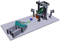
Gear lever

Several features can be checked on gear levers: either the dimensional conformity of their components – housings levers, etc., or their functionality – i.e positions of the gears, fixations, etc. Defining well these features from the beginning can enable us to propose you a wide range of solutions, from basic production fixtures to automated fixtures.

Our checking fixtures are produced in aluminium, the components submitted to wear-and-tear are produced in steel. Tolerances for RPS (fixation points) and dial indicator points: ±0.05mm. Tolerances for simulation blocks: ±0.1mm.

Minimum documentation: dimensional report of your checking fixture, 2D assembly drawing, assembly CAD. Optional documentation: R&R report, user manual, stabilization certificate.

Gear lever test bench
  • Control of the functionality of the lever: position of the lever in its different gears, and maximum position of the connectors of the lever connection cables
  • Control of the position by producing a master part of the lever knob, and measuring it by dial indicator
  • Control of the position of the cables connectors by mounting them on mobile fixation elements: the position of these fixation elements is measured by a digital ruler
  • Fastening of the part by its fixation points, located on the lever housing, by screws and clamps
  • Optional: possibility of controlling several versions of lever on one checking fixture. Tecnomatrix checks the factibility of this option.
Gear lever housing
  • Fastening of the part on its four fixation holes by 4 screws
  • Control of the position of the different holes of the part by a digital ruler mounted on a sliding rail and a control pin mounted on foldable arms
  • Control of the diameters and concentricity of the holes by Go/No Go pins
Complete checking fixture
  • Fastening of the part on its housing by 4 screws
  • Control of the height of the lever with a Go/No Go feeler
  • Control of the position of the knob screw and lever upper area by a U-shaped pin
  • Control of the force of movement of the lever when switching from one gear to another by a dynamometer connected to a light: when the lever is at the position of one of the gears, the light turns on. The operator has to check the force measured by the dynamometer once the light is on
  • Control of the force of movement when lifting the lever up for the gear lever by dynamometer

Contact us for more information

    *Name

    *Company

    *Email

    *Phone-number

    Subject

    *Message

    Scroll to Top